
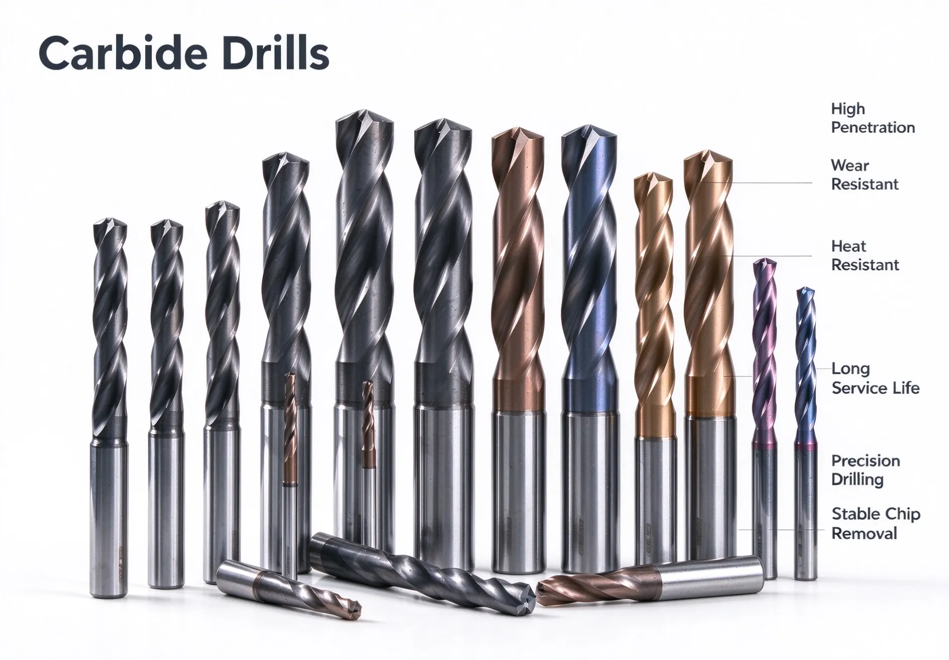
Drills
Steel, Alloy Steel, Cast Iron Solid Carbide Drills
High-performance carbide drill optimized for stainless steel, ductile iron and alloy steel. Stable cutting performance, longer tool life and improved productivity for hydraulic components, elevator parts and general machining.
Specifications
- Spec 1
- Double curved surface design, sickle shaped blade, enhances chip breaking effect;
- Spec 1
- The chip removal groove polishing process helps to improve the smoothness of iron chip discharge;
- Spec 1
- New coating technology provides excellent processing life;
Product Overview
Hard alloy drill bits are made of hard alloy materials such as tungsten carbide as the main cutting components, complete hard alloy rods, and precision ground using a 5-axis fully automatic machining center. Hard alloy drill bits have a wide range of versatility, with high strength, high hardness, fast cutting speed, wear resistance, and good red hardness, making them suitable for processing various materials of parts. Hard alloy drill bits can be divided into two types based on their cooling structure: those without cooling holes and those with cooling holes.
Introduction
Item | Parameter |
|---|---|
Processing Material | ISO Workpiece Material Groups P, M, K, N, S, H |
Application Industry: | Construction machinery industry, energy industry, and automotive industry |
Overall Tool Length | 60‑120 mm |
Number of Cutting Teeth(Z) | 2 teeth,4 teeth,6 teeth |
Coolant Option | External coolant / Internal through coolant |
PCD Grain Grades | Fine grain, medium grain, coarse grain |
Tool specifications | Processing range D3-D20; Head tolerance h7; |
Machining Type | Precision drilling, finishing reaming, combined drill‑reaming |
Custom Service | Custom diameter, stepped profile, special flute geometry, special shank (BT / HSK) |
Tool parameters
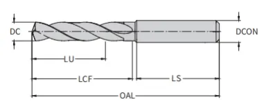
Part Number | Dc(h7) mm | Lu mm | OAL mm | LCF mm | LS mm | DCON(h60) mm |
D105-05-03000A0 | 3.0 | 23 | 66 | 28 | 36 | 4 |
D105-05-03100A0 | 3.1 | 23 | 66 | 28 | 36 | 4 |
D105-05-03200A0 | 3.2 | 23 | 66 | 28 | 36 | 4 |
D105-05-03300A0 | 3.3 | 23 | 66 | 28 | 36 | 4 |
D105-05-03400A0 | 3.4 | 23 | 66 | 28 | 36 | 4 |
D105-05-03500A0 | 3.5 | 23 | 66 | 28 | 36 | 4 |
D105-05-03600A0 | 3.6 | 23 | 66 | 28 | 36 | 4 |
D105-05-03700A0 | 3.7 | 23 | 66 | 28 | 36 | 4 |
D105-05-03800A0 | 3.8 | 29 | 74 | 36 | 36 | 4 |
D105-05-03900A0 | 3.9 | 29 | 74 | 36 | 36 | 4 |
D105-05-04000A0 | 4.0 | 29 | 74 | 36 | 36 | 4 |
D105-05-04100A0 | 4.1 | 29 | 74 | 36 | 36 | 6 |
D105-05-04200A0 | 4.2 | 29 | 74 | 36 | 36 | 6 |
D105-05-04300A0 | 4.3 | 29 | 74 | 36 | 36 | 6 |
D105-05-04400A0 | 4.4 | 29 | 74 | 36 | 36 | 6 |
D105-05-04500A0 | 4.5 | 29 | 74 | 36 | 36 | 6 |
D105-05-04600A0 | 4.6 | 29 | 74 | 36 | 36 | 6 |
D105-05-04700A0 | 4.7 | 29 | 74 | 36 | 36 | 6 |
D105-05-04800A0 | 4.8 | 35 | 82 | 44 | 36 | 6 |
D105-05-04900A0 | 4.9 | 35 | 82 | 44 | 36 | 6 |
D105-05-05000A0 | 5.0 | 35 | 82 | 44 | 36 | 6 |
D105-05-05100A0 | 5.1 | 35 | 82 | 44 | 36 | 6 |
D105-05-05200A0 | 5.2 | 35 | 82 | 44 | 36 | 6 |
D105-05-05300A0 | 5.3 | 35 | 82 | 44 | 36 | 6 |
D105-05-05400A0 | 5.4 | 35 | 82 | 44 | 36 | 6 |
D105-05-05500A0 | 5.5 | 35 | 82 | 44 | 36 | 6 |
D105-05-05600A0 | 5.6 | 35 | 82 | 44 | 36 | 6 |
D105-05-05700A0 | 5.7 | 35 | 82 | 44 | 36 | 6 |
D105-05-05800A0 | 5.8 | 35 | 82 | 44 | 36 | 6 |
D105-05-05900A0 | 5.9 | 35 | 82 | 44 | 36 | 6 |
D105-05-06000A0 | 6.0 | 35 | 82 | 44 | 36 | 6 |
D105-05-06100A0 | 6.1 | 43 | 91 | 53 | 36 | 8 |
D105-05-06200A0 | 6.2 | 43 | 91 | 53 | 36 | 8 |
D105-05-06300A0 | 6.3 | 43 | 91 | 53 | 36 | 8 |
D105-05-06400A0 | 6.4 | 43 | 91 | 53 | 36 | 8 |
D105-05-06500A0 | 6.5 | 43 | 91 | 53 | 36 | 8 |
D105-05-06600A0 | 6.6 | 43 | 91 | 53 | 36 | 8 |
D105-05-06700A0 | 6.7 | 43 | 91 | 53 | 36 | 8 |
D105-05-06800A0 | 6.8 | 43 | 91 | 53 | 36 | 8 |
D105-05-06900A0 | 6.9 | 43 | 91 | 53 | 36 | 8 |
D105-05-07000A0 | 7.0 | 43 | 91 | 53 | 36 | 8 |
Carbide Drill Failure Modes & Countermeasures
Failure Mode | Cause Analysis | Solutions |
|---|---|---|
Flank Wear | Flank wear occurs due to friction between workpiece and the flank face. | • Reduce cutting speed• Increase feed rate• Increase coolant flow (e.g. by raising coolant pressure) |
Built-up Edge (BUE) | Built-up edge is caused by micro cold welding of workpiece material on the cutting edge. | • Increase cutting speed• Increase coolant flow (e.g. by raising coolant pressure) |
Chipping | Chipping results from thermal cracks, cutting impact, vibration and excessive wear resistance of tool material. | • Replace or recondition tools earlier• Improve system rigidity (workpiece / tool) |
Plastic Deformation | High heat generation and mechanical load lead to plastic deformation. | • Reduce feed rate• Increase coolant flow (e.g. by raising coolant pressure) |
Crater Wear | Crater wear on rake face caused by diffusion and friction. | • Increase cutting speed• Increase feed rate• Raise coolant pressure |
Processing Parameters
ISO Group | Workpiece Material | Brinell Hardness (HB) | Tensile Strength Rm (N/mm²) | External CoolingVc (m/min) | External CoolingFeed Code | Internal CoolingVc (m/min) | Internal CoolingFeed Code |
|---|---|---|---|---|---|---|---|
P | Unalloyed Steel C≤0.25% (Annealing) | 125 | 428 | 100-110 | F | 110-120 | F |
P | Unalloyed Steel 0.25<C≤0.55% (Annealing) | 190 | 639 | 80-100 | E | 100-110 | E |
P | Unalloyed Steel 0.25<C≤0.55% Q&T | 210 | 708 | 80-100 | E | 100-110 | E |
P | Unalloyed Steel C>0.55% (Annealing) | 190 | 639 | 90-100 | E | 100-110 | E |
P | Unalloyed Steel C>0.55% Q&T | 300 | 1013 | 70-80 | D | 80-90 | D |
P | Free cutting steel (short chips) (Annealing) | 220 | 745 | 100-120 | F | 110-120 | F |
P | Low-alloy Steel Annealing | 175 | 591 | 80-100 | E | 80-110 | E |
P | Low-alloy Steel Q&T | 285 | 960 | 70-90 | D | 70-90 | D |
P | Low-alloy Steel Q&T | 380 | 1282 | 40-50 | C | 40-50 | C |
P | Low-alloy Steel Q&T | 430 | 1477 | 35-45 | B | 35-45 | B |
P | High Alloy Tool Steel Annealing | 200 | 675 | 75-85 | D | 75-85 | D |
P | High Alloy Tool Steel Quenching & Tempering | 300 | 1013 | 60-70 | C | 60-70 | C |
P | High Alloy Tool Steel Quenching & Tempering | 400 | 1361 | 50-60 | C | 50-60 | C |
M | Stainless Steel Ferrite/Martensite, Annealing | 200 | 675 | 70-80 | D | 80-90 | D |
M | Stainless Steel Martensite, Q&T | 330 | 1114 | 45-60 | C | - | - |
M | Austenitic Stainless Steel, Quenched | 200 | 675 | 40-50 | C | - | - |
M | Austenitic precipitation hardening stainless steel (PH stainless steel) | 300 | 1013 | 40-50 | C | - | - |
M | Austenitic ferritic Duplex stainless steel | 230 | 778 | 30-40 | B | - | - |
K | Malleable Cast Iron Ferrite | 200 | 400 | 110-130 | G | 120-130 | G |
K | Malleable Cast Iron Pearlite | 260 | 700 | 85-100 | G | 90-110 | G |
K | Grey Cast Iron Low tensile strength | 180 | 200 | 110-120 | H | 120-130 | H |
K | Grey Cast Iron High tensile strength/austenite | 245 | 350 | 80-100 | G | 90-110 | G |
K | Ductile Cast Iron Ferrite | 155 | 400 | 110-120 | G | 120-130 | H |
K | Ductile Cast Iron Pearlite | 265 | 700 | 60-80 | F | 60-80 | F |
K | Creep Graphite Cast Iron GGV (CGI) | 230 | 400 | 60-80 | F | 60-80 | F |
N | Forged Aluminum Alloy Non-time processing | 30 | - | 200-300 | G | 300-400 | G |
N | Forged Aluminum Alloy Time sensitive processing | 100 | 340 | 200-300 | G | 300-400 | G |
N | Cast Aluminum Alloy ≤12% silicon, Non aging treatment | 75 | 260 | 160-220 | H | 180-240 | H |
N | Cast Aluminum Alloy ≤12% silicon, Age treatable | 90 | 310 | 160-200 | H | 180-200 | H |
N | Cast Aluminum Alloy >12% silicon, Non aging treatment | 130 | 450 | 130-160 | G | 140-180 | G |
N | Magnesium Alloy | 70 | 250 | - | - | - | - |
N | Copper and Copper Alloys Non alloy, electrolytic copper | 100 | 340 | 120-160 | C | 140-170 | D |
N | Copper and Copper Alloys Brass, Bronze, Red Brass | 90 | 310 | 110-140 | E | 120-140 | E |
N | Copper and Copper Alloys Copper alloy, short chips | 110 | 380 | 120-150 | F | 140-180 | F |
N | Copper and Copper Alloys High strength Ampco alloy | 300 | 1010 | 45-60 | B | 45-60 | B |
S | Superalloy Iron based (Annealing) | 200 | 680 | 30-40 | B | (Time limit) | - |
S | Superalloy Iron based | 280 | 940 | 20-25 | A | - | - |
S | Superalloy Nickel based or cobalt based (Annealing) | 250 | 840 | 20-30 | B | (Time limit) | - |
S | Superalloy Nickel based or cobalt based | 350 | 1180 | 10-15 | A | - | - |
S | Superalloy (Casting) | 320 | 1080 | 15-25 | A | - | - |
S | Titanium Alloy Pure titanium | 200 | 680 | 30-40 | B | 40-50 | C |
S | Titanium Alloy Alpha & beta phase alloys, Aged treatment | 375 | 1260 | 20-30 | A | 25-35 | B |
S | Titanium Alloy β - phase alloy | 410 | 1400 | 10-15 | A | - | - |
S | Tungsten Alloy | 300 | 1010 | - | - | - | - |
S | Molybdenum Alloy | 300 | 1010 | - | - | - | - |
H | Quenched steel 50HRC | - | - | 20-35 | A | 20-35 | A |
H | Quenched steel Q&T 55HRC | - | - | - | - | - | - |
H | Quenched steel Q&T 60HRC | - | - | - | - | - | - |
H | Quenched Cast iron Q&T 55HRC | - | - | - | - | - | - |
Feed Reference Table (Feed per revolution f, mm/rev)
Matches the Feed Code (A/B/C/D/E/F/G/H) used in D105 drill cutting parameter table
Drill Diameter (mm) | A | B | C | D | E | F | G | H |
|---|---|---|---|---|---|---|---|---|
3 | 0.03 | 0.04 | 0.05 | 0.06 | 0.08 | 0.10 | 0.12 | 0.14 |
4 | 0.04 | 0.05 | 0.06 | 0.08 | 0.10 | 0.12 | 0.14 | 0.16 |
5 | 0.05 | 0.06 | 0.07 | 0.09 | 0.10 | 0.12 | 0.16 | 0.18 |
6 | 0.05 | 0.07 | 0.08 | 0.10 | 0.12 | 0.15 | 0.18 | 0.20 |
8 | 0.06 | 0.08 | 0.10 | 0.12 | 0.15 | 0.18 | 0.20 | 0.23 |
10 | 0.08 | 0.10 | 0.12 | 0.14 | 0.18 | 0.20 | 0.24 | 0.28 |
12 | 0.10 | 0.12 | 0.14 | 0.18 | 0.20 | 0.24 | 0.28 | 0.32 |
14 | 0.10 | 0.14 | 0.18 | 0.20 | 0.24 | 0.28 | 0.32 | 0.34 |
16 | 0.12 | 0.15 | 0.18 | 0.20 | 0.25 | 0.30 | 0.34 | 0.36 |
20 | 0.15 | 0.16 | 0.20 | 0.25 | 0.30 | 0.34 | 0.37 | 0.40 |